Abstract
Momentary switches are important building blocks to prototype novel physical user interfaces and enable tactile, explicit as well as eyes-free interactions. Unfortunately, typical representatives, such as push-buttons or pre-manufactured membrane switches, often do not fulfill individual design requirements and lack customization options for rapid prototyping. With this work, we present Pushables, a DIY fabrication approach for producing thin, bendable and highly customizable membrane dome switches. Therefore, we contribute a three-stage fabrication pipeline that describes the production and assembly on the basis of differently demanding prototyping methods making our approach suitable for technology-enthusiastic makers, researchers, fab labs and others who require custom membrane switches in small quantities. To demonstrate the wide applicability of Pushables, we present application examples from ubiquitous, mobile and wearable computing.
Publications & Articles
@article{klamka2018_make,
author = {Konstantin Klamka and Raimund Dachselt},
title = {Folientaster selbstgemacht – von Hand oder mit der Maschine},
year = {2019},
month = {01},
location = {Hannover},
pages = {84--85},
url = { https://shop.heise.de/katalog/community-projekte-bc9a98?wt_pdsrc=productList},
publisher = {Kreativ mit Technik | Make - Heise; Maker Media GmbH}
}List of additional material

@inproceedings{klamka2018_pushables,
author = {Konstantin Klamka and Raimund Dachselt},
title = {Pushables: A DIY Approach for Fabricating Customizable and Self-Contained Tactile Membrane Dome Switches},
booktitle = {The 31st Annual ACM Symposium on User Interface Software and Technology Adjunct Proceedings},
year = {2018},
month = {10},
location = {Berlin, Germany},
pages = {1--4},
numpages = {3},
doi = {10.1145/3266037.3266082},
url = {https://doi.org/10.1145/3266037.3266082},
acmid = {3266082},
publisher = {ACM},
address = {New York, NY, USA},
keywords = {paper button, tactile, printed electronics, interactive paper, haptic, membrane switch, dome switch}
}List of additional material
Video
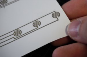
1 – Circuit Layer
1.1 – Copper Tape
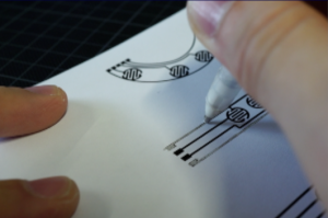
1.2 – Conductive Pens
1.3 – Conductive Inkjet-Printing
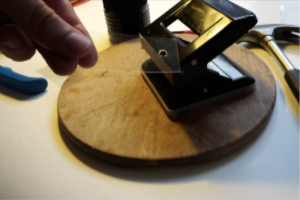
2 – Spacer Layer
2.1 – Office Puncher
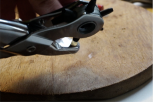
2.2 – Punch Pliers
2.3 – Hole Punch
3 – PVC Dome Layer
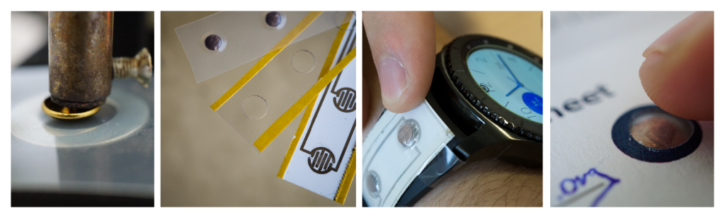
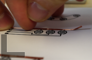
In order to realize membrane buttons with a great tactile feel and nice perceptible counter pressure, we introduce three embossing processes that show how dome-shaped polyester overlays can be DIY fabricated.
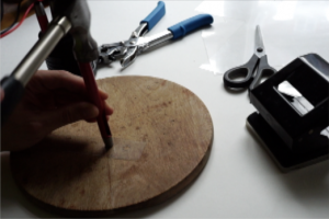
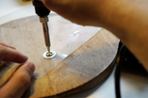
3.1 Manual Embossing
Part List
| Image | Part | Description |
|---|---|---|
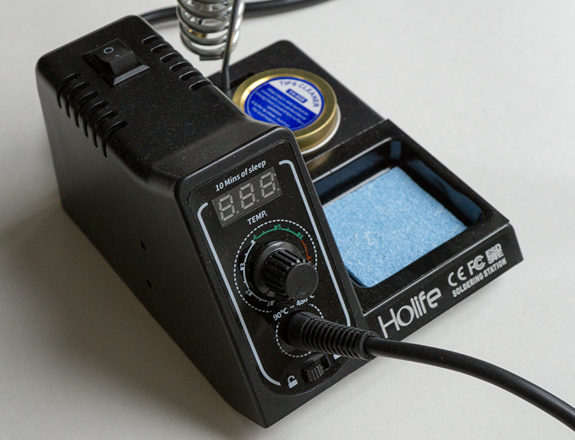 |
Solder Iron* *recommented with adjustable temperature control (100°C) |
We used an inexpensive temperatur-controlled HoLife solder iron station. |
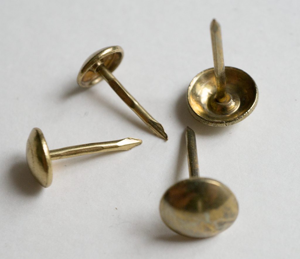 |
Upholstery Nails | Depending on your solder iron you additionally need a screw driver or a drilling machine and a hammer to securely fix the upholstery nails at the solder tip. |
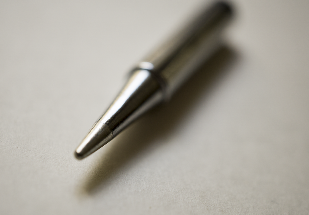 |
Solder Iron Tip | We modified a standard exchangeable solder iron tip. |
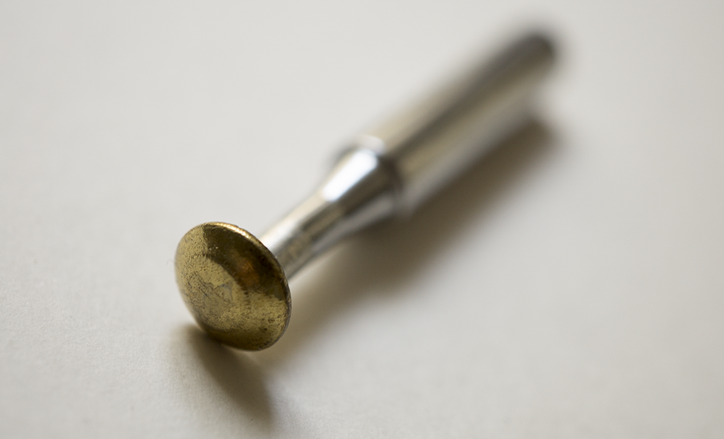 |
Solder Iron Tip with Upholstery Nail | We modified a standard exchangeable solder iron tip with upholstery nail. |
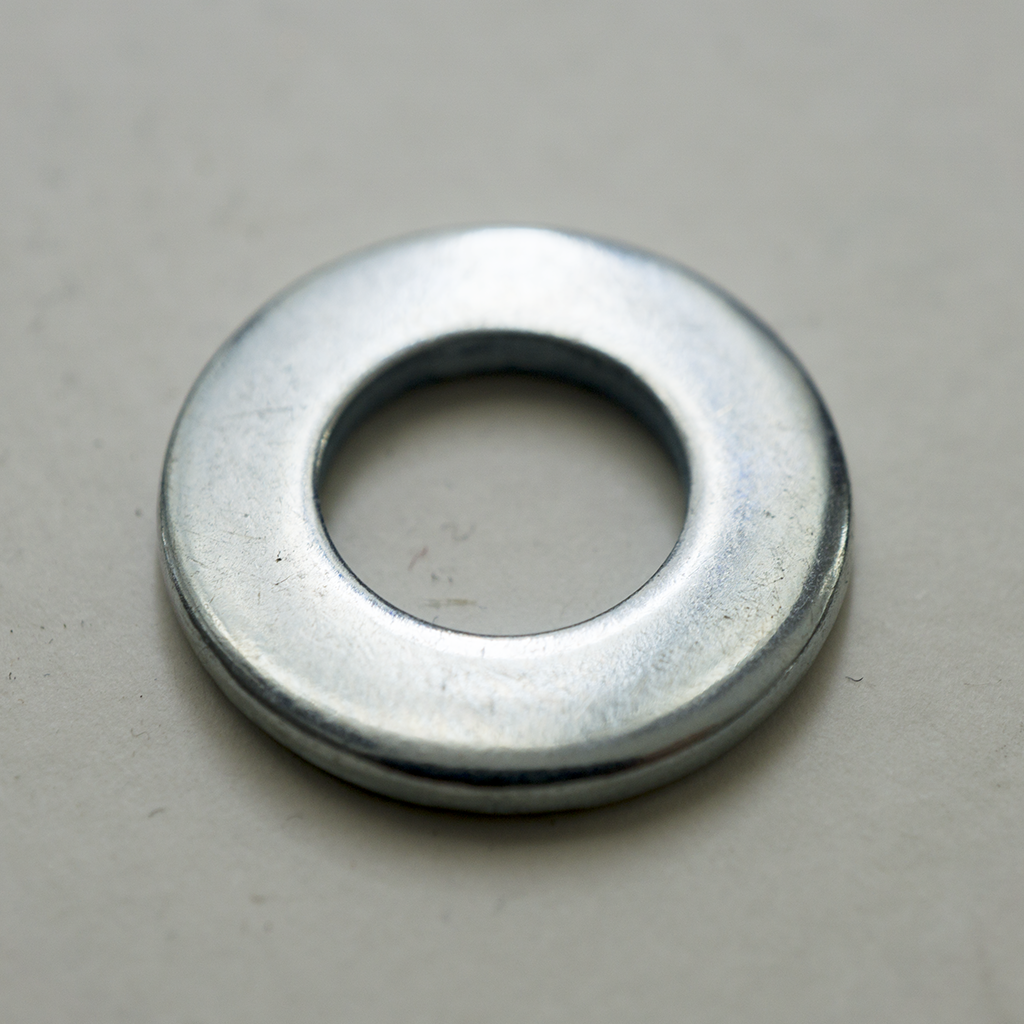 |
Washer | We used a standard washer as a spacer for the embossing process. |
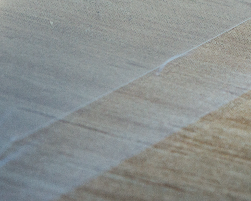 |
PVC Foil | We used Leitz Copysafe 4100 transparent envelope. |
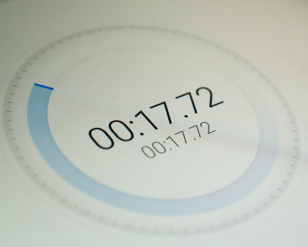 |
Stopwatch e.g., smartphone app |
Since the timing for the embossing process is very important, you need a stopwatch. |
3.2 Semi-automatic Embossing
Part List
| Image | Part | Description |
|---|---|---|
|
Solder Iron*
*recommented with adjustable temperature control (100°C) |
We used an inexpensive temperatur-controlled HoLife solder iron station. |
|
Upholstery Nails | Depending on your solder iron you additionally need a screw driver or a drilling machine and a hammer to securely fix the upholstery nails at the solder tip. |
|
Washer | We used a standard washer as a spacer for the embossing process. |
 |
Access to 3D-Printer | In order to 3D print all construction parts you will need access to basic 3D-Printer. We used a modified PP3DP UP! Mini from Tiertime with a black ABS filament. |
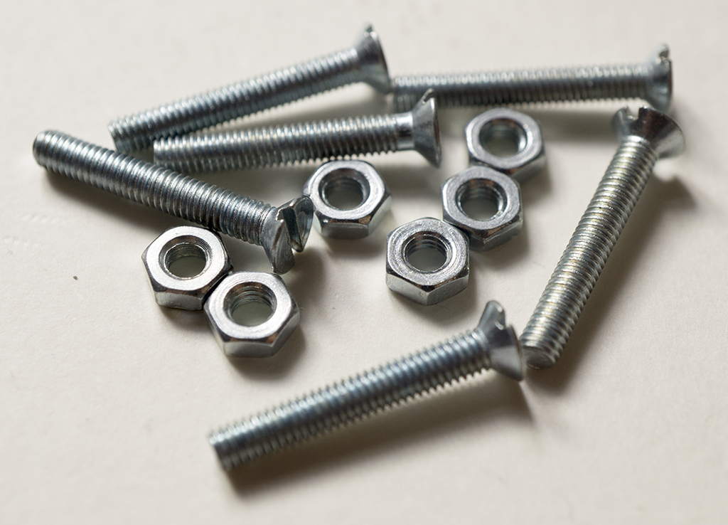 |
Screws and Nuts | We used several metric screws and nuts to fix all 3D printed parts and electronics. |
 |
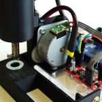
Stepper Motor | To realize an adjustable z-axis, we used a simple 12V stepper motor that we expanded from an old, discarded printer. Of course you can use every stepper motor that have enough force to lift up a solder iron. |
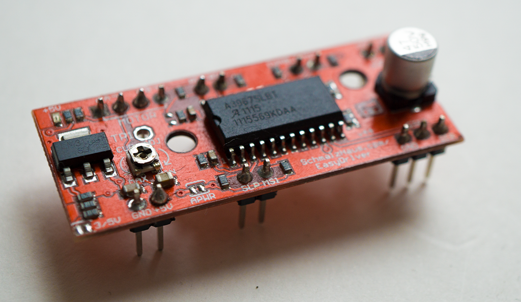 |
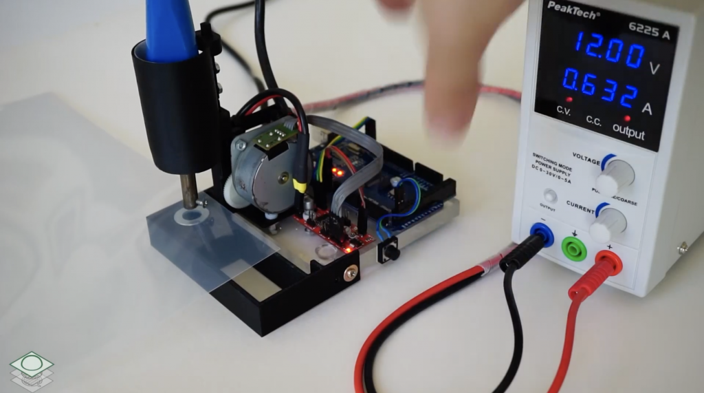
Stepper Motor Driver Board | We used a SparkFun EasyDriver – Stepper Motor Driver to control our z-axis stepper motor. The board is powered with 12V from our adjustable power supply and is attached to the Arduino. |
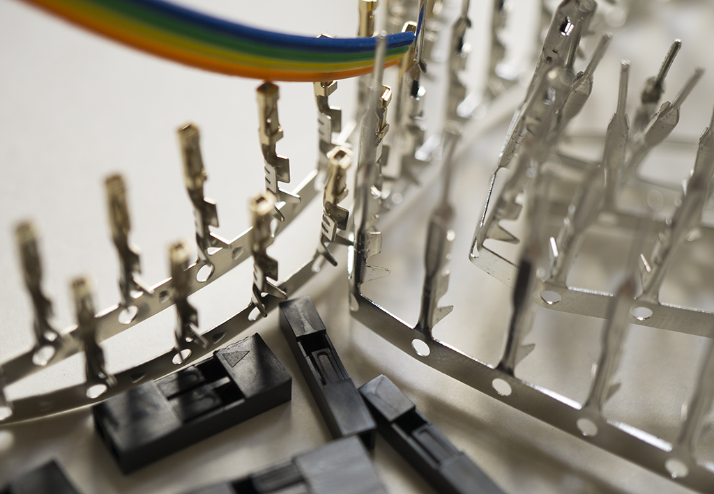 |
Cable, Crimp Contacts and Housings | We used several standard pin headers to design our semi-automatic embossing machine as flexible as possible without hardwiring all components. |
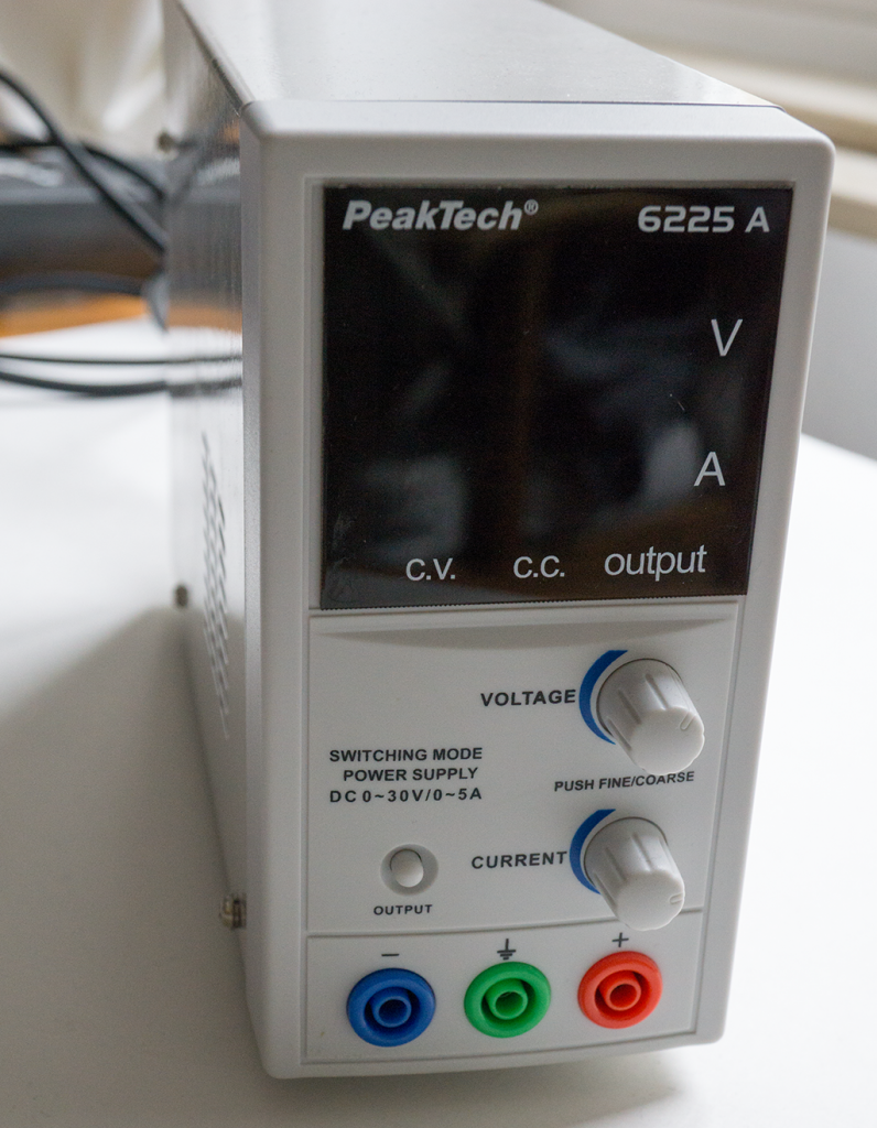 |
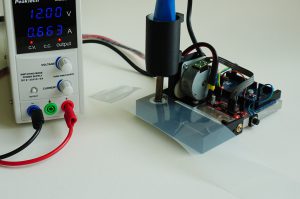
Power Supply | We used a laboratory switching power supply from Peaktech (Model: 6225 A) that provides 0-30 DC voltage and 0 – 5A ampere. To run our semi-automatic embossing machine including the Arduino and its stepper motor, we adjust the power supply to 12V and 2A. |
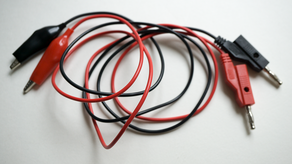 |
Safety laboratory cables | We used safety laboratory cables to hook up the stepper motor driver board and Arduino micro-controller. |
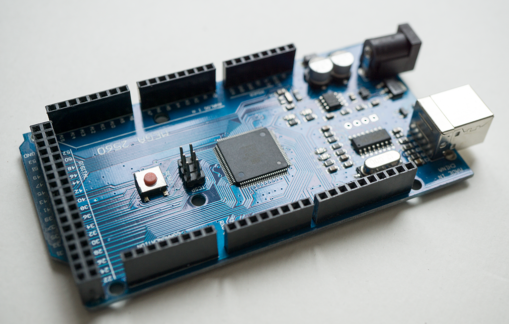 |
Arduino compatible Microcontroller | Since the Arduino only had to control a stepper motor and needs to be triggered, there are no huge requirements to the micro-controller. We used a Arduino Mega 2560 R3, however, every smaller Arduino, such as an Arduino Uno or Micro will perfectly work, too. |
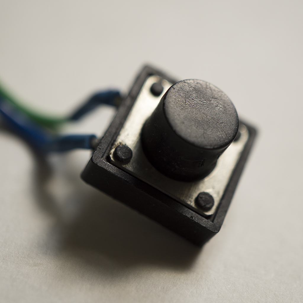 |
Push-Button | A push-button acts as a trigger to start the embossing process. |
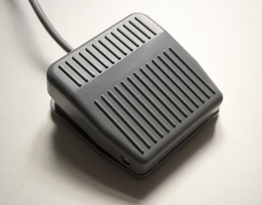 |
Foot Switch (optional) |
As an alternative trigger mechanism, we integrated a foot switch enabling a hand-free start of the embossing process. This could be helpful for very precise manual alignments. |
|
PVC Foil | We used Leitz Copysafe 4100 transparent envelope. |
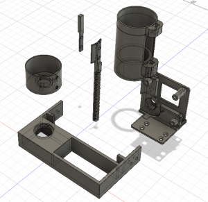
3D-Printed Parts
CAD Model
Printed Parts
Download
You can download every part as a STL file.
Arduino Sketch
/* Pushables: A DIY Approach for Fabricating Customizable
 * and Self-Contained Tactile Membrane Dome Switches
 * - Konstantin Klamka & Raimund Dachselt -
 *
 * Sketch for a simple semi-automatic embossing machine.
 *
 * This sketch controls a stepper motor. By triggering a
 * push-button the motor moves a linear actuator 534 steps
 * down (see EMBOSSING_DISTANCE), waits four secounds (see
 * EMBOSSING_TIME) and moves a the linear actuator back in
 * its position. The temperature-controlled solder iron
 * with the attached upholstery nail is not part of the
 * arduino sketch since we use a commercial solder iron
 * station.
 *
 * created 2018 by
 * Konstantin Klamka
 * Interactive Media Lab Dresden, Germany
 *
 * This example code is in the public domain.
 *
 * Project website:
 * http://www.imld.de/pushables/
 *
 * ----------------------------------------
 *
 * The hardware:
 * Arduino Mega 2560 Rev3, Easy Driver Stepper Motor Driver,
 * stepper motor from an old printer, laboratory power supply
 * temperature-controlled solder iron with an attached upholstery
 * nail, linear actuator (we used 3D-printed parts that are
 * available on our project website).
 *
 * The circuit:
 *
 * push-button
 * pin 53 and ground
 *
 * Easy Driver Stepper Motor Driver:
 * DIR  : pin 12
 * STEP : pin 13
 * GND  : ground
 * PWR IN: external laboratory power supply (12V, 1A)
 *
 * ----------------------------------------
  */

// ---- Pins ------
#define DIR_PIN 12
#define STEP_PIN 13
#define BUTTON_PIN 53

// ---- Embossing Parameters ------
#define EMBOSSING_DISTANCE  534  // steps
#define EMBOSSING_TIME      4000 // milliseconds

// ---- Setup ------
void setup() {

  // Set Pin Modes
  pinMode(DIR_PIN, OUTPUT);
  pinMode(STEP_PIN, OUTPUT);
  pinMode(BUTTON_PIN, INPUT_PULLUP);

  digitalWrite(DIR_PIN, HIGH);
  digitalWrite(STEP_PIN, LOW);
}

// ---- loop ------
void loop() {

  // Read the push-button value into a variable
  int button_state = digitalRead(BUTTON_PIN);

  // Keep in mind the pull-up means the pushbutton's
  // logic is inverted. It goes HIGH when it's open,
  // and LOW when it's pressed.
  if (button_state == LOW){

    digitalWrite(DIR_PIN, HIGH);

    // move temperature-controlled solder iron
    // with the attached upholstery nail down
    for(int i = 0; i<EMBOSSING_DISTANCE;i++){
      digitalWrite(STEP_PIN, LOW);
      delay(1);
      digitalWrite(STEP_PIN, HIGH);
      delay(1);
    }

    // wait while the heated upholstery nail
    // embosses the PVC foil...
    delay(EMBOSSING_TIME);

    // move temperature-controlled solder iron
    // with the attached upholstery nail up...
    digitalWrite(DIR_PIN, LOW);
    for(int i = 0; i<EMBOSSING_DISTANCE;i++){
      digitalWrite(STEP_PIN, LOW);
      delay(1);
      digitalWrite(STEP_PIN, HIGH);
      delay(1);
    }

    digitalWrite(DIR_PIN, HIGH);
    }
}
Download the sketch here: pushables.ino
3.3 Automatic Embossing
Part List
| Image | Part | Description |
|---|---|---|
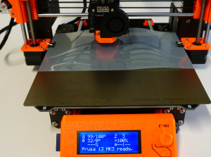
|
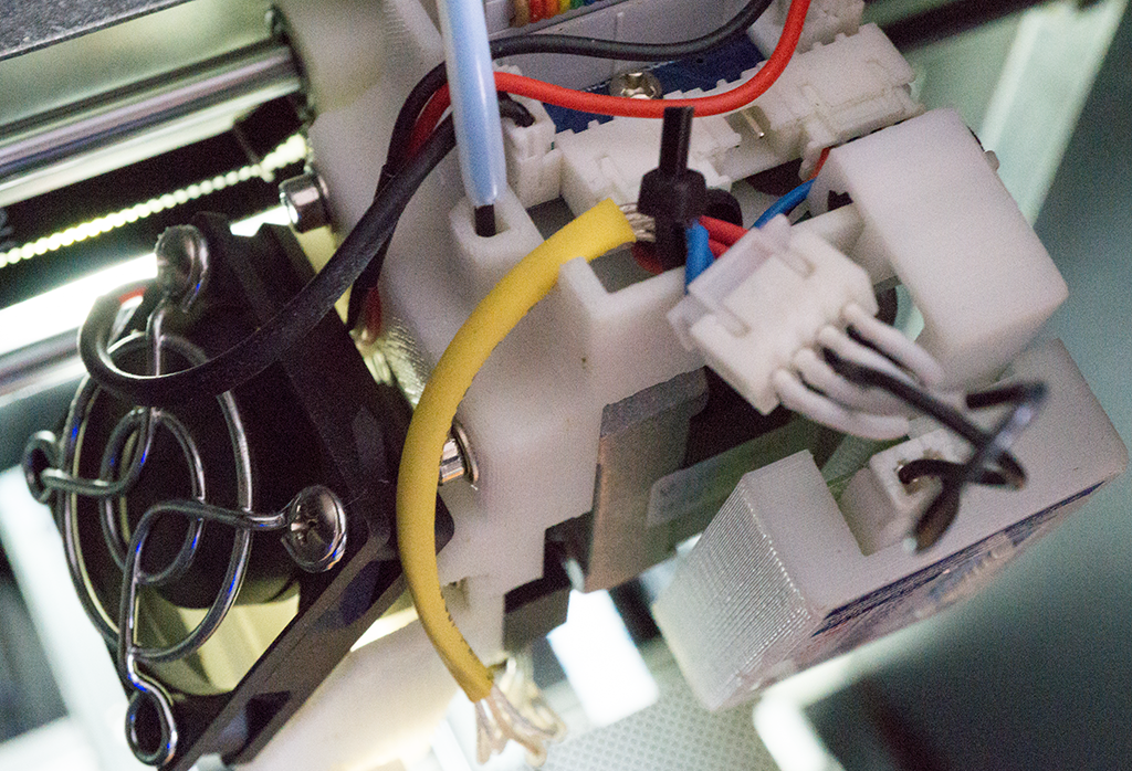
3D-Printer | In order to realize our automatic embossing machine, we used a Original Prusa i3 MK3 with our custom embossing nozzle. |
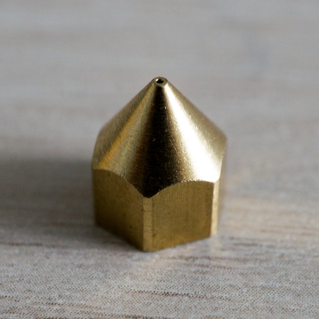 |
Nozzle | In order to modify the nozzle, we built on a new replacement nozzle for our 3D printer. |
|
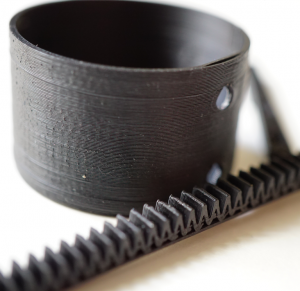
Upholstery Nails | Depending on your solder iron you additionally need a screw driver or a drilling machine and a hammer to securely fix the upholstery nails at the solder tip. |
|
PVC Foil | We used Leitz Copysafe 4100 transparent envelope. |
Basic G-code Procedure
| G-code | Description |
|---|---|
| G28 | Perform Homing Routine: home all axes (X, Y, and Z) |
| G1 Z20 F1200 | Move the Z-axis to Z=20mm at a slower speed of 1200 mm/min |
| M104 S100 T0 | Start heating T0 to 100 degrees Celsius |
| M109 S100 T0 | Wait for T0 to reach 100 degrees before continuing with any other commands |
| G1 X50 Y50 F2400 | Move to the X=50 Y=50 position on the bed at a speed of 2400 mm/min |
| G1 Z1 F1200 | Move the Z-axis to Z=1mm at a slower speed of 1200 mm/min |
| G4 P4000 | Wait four seconds |
| G1 Z20 F1200 | Move the Z-axis to Z=20mm at a slower speed of 1200 mm/min |
| M104 S0 T0 | Start cooling T0 to 0 degrees Celsius |
| G1 X0 Y0 F2400 ; | Move to the X=50 Y=50 position on the bed at a speed of 2400 mm/min |
G-code Template
G28
G1 Z20 F1200
M104 S100 T0
M109 S100 T0
G1 X50 Y50 F2400
G1 Z1 F1200
G4 P4000
G1 Z20 F1200
M104 S0 T0
G1 X0 Y0 F2400 ;
Download the G-code file here: pushables.gcode